Hobby project: Hollow Shaft “Turret”
Published:
updated on 2022/07/10
Youtube video of demo 1.
Hollow Shaft “Turret” is a 3D printed, motorized mechanism for tracking in 2 or 3 axis. The hollow shaft refers to the mechanical design of rotation, such that it takes into account cable management. For instance, lets have a camera mounted on single axis that is connected to PC via cable. If the camera rotates 360 degrees around its axis the cable wounds around the mechanism providing the rotation. The more the camera rotates, the more cable is wound around the mechanism.
To address the problem of cable management on rotating mechanisms with multiple-axis, it is ideal to come with a solutions, than prevents a cable winding around the parts of the mechanism all together. One such solution is to have a hollow shaft through which the cable runs, such that there is nothing that the cable needs to revolve around in the first place (except its own axis).
To explain the name fully, the word “turret” refers to the rotation capability, and I hope to come up with some cool acronym later, such as:
T inkerer’s
U niversal
R otating
R obot (with)
E ffective
T echnique for cable managenemnt
P.S. You are very welcome to contribute to this project with better acronym.
Progress
- decide of-the-shelf parts to settle on dimensions
- get mechanical parts (6810 bearings and M3 screws)
- design the first prototype of the “wheel”
- 3D print the “wheel”
- design the base-plate which holds everything together
- design multi-axis mechanism
- 3D print everything from correct material
- pick proper NEMA17 stepper motors (with proper torque)
get timing pulley and timing belt (preferably 10mm wide)(design change)- get stepper motor drivers (based on TMC2209)
- get arduino with CNC shield
- [ ]
Revision 4 (version 5)
Introdcing minor changes to address minor issues when testing rev. 4 ver. 4 with stepper-motors attached and controlled via GRBL. The control of 2 axis (but 3 motors, 1 motor for X-axis, 2-motors for Y-axis) has been testing using the following commands:
# set the rates for axis X, Y and Z
$110=800.00
$111=800.00
$112=800.00
# perform the movement
G0 X0Y100Z100
G0 X100Y0Z0
A set of instructions can be found here.
A final touch is a custom case for Arduino UNO with CNC shield depicked below. 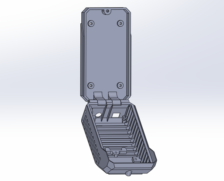
Check soon for a video of moving Turret rev.4 ver. 5 and STL files for the whole project
Revision 4 (version 4)
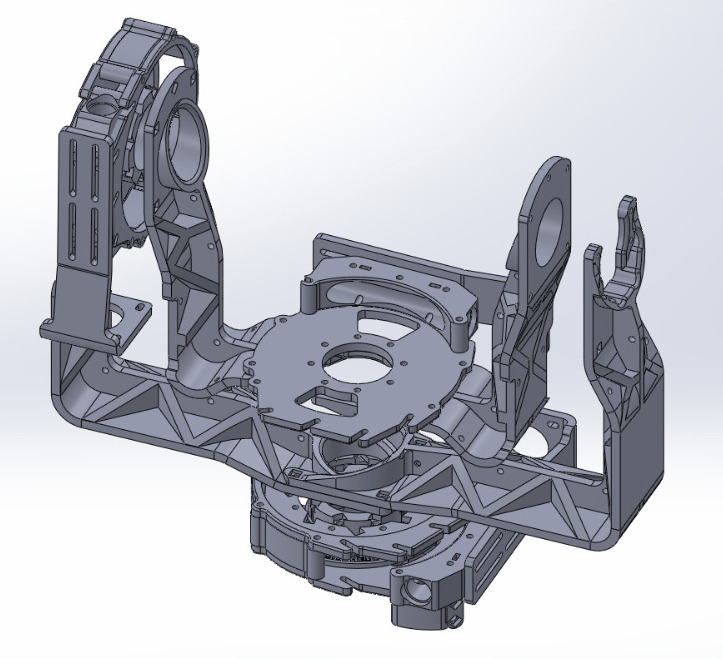
This version is under print at the moment. If no major setbacks are found, this should be considered the final working prototype, officialy being released as Turret v1.0!
Revision 4 (version 3)
Since the axis-mechanism, a.k.a the hollow-shaft axis-mechanism is settled, it is time to work on the turret itself. The first iteration of arms with 2-axis looks like this:
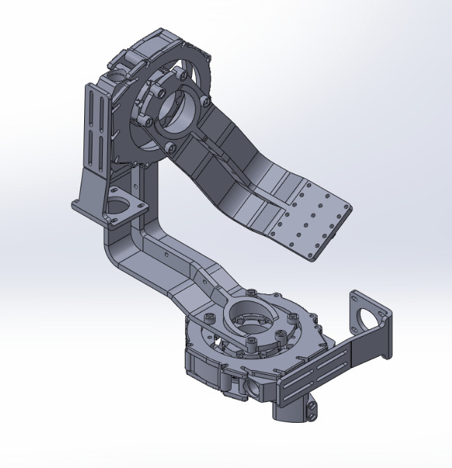
Once printed, the arms had more flex as expected. To see whether structure can be made tougher, I have asked my brother Thomas Garaj to simulate a ribbed and smooth version of the major axis-arms:
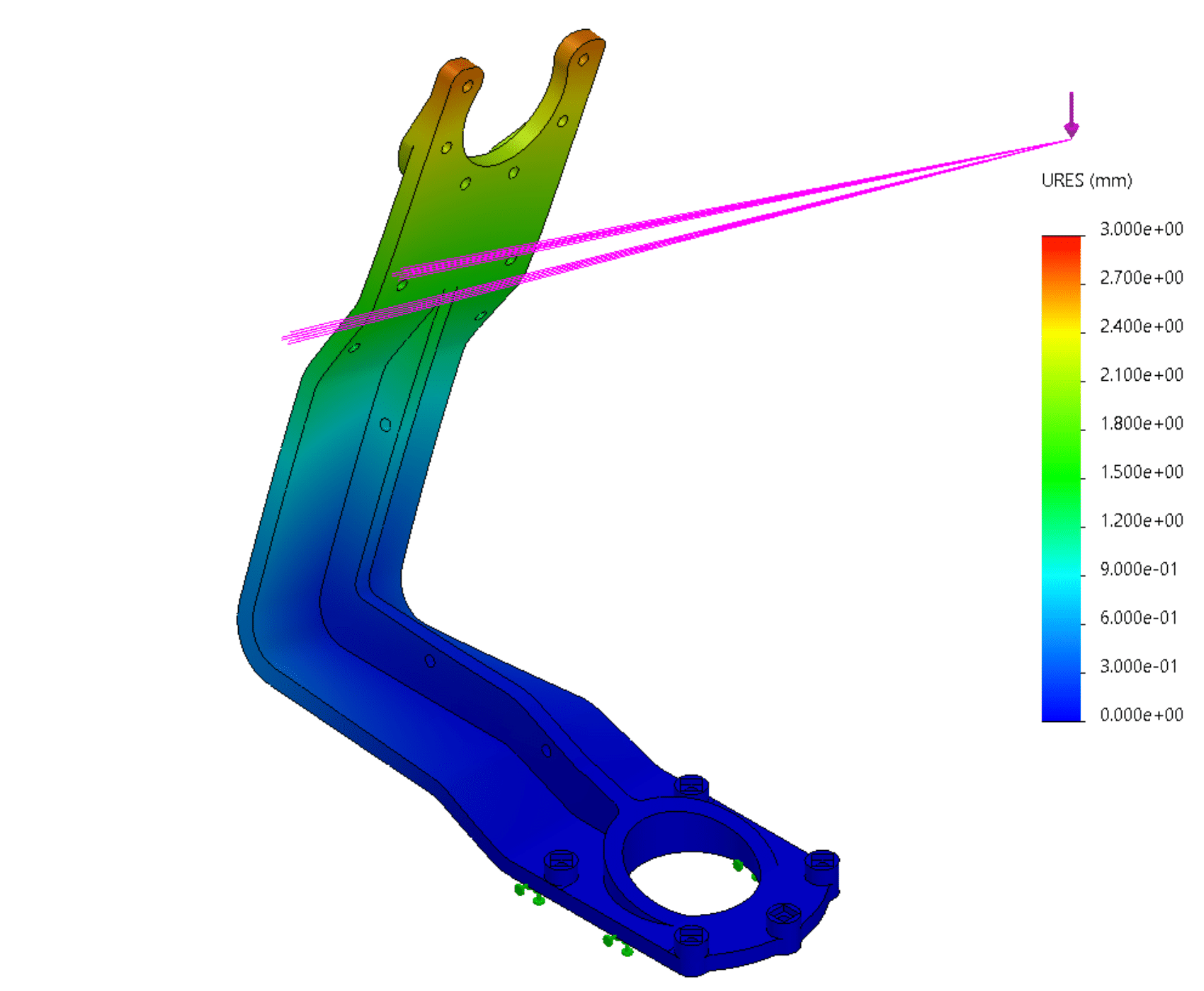
and the ribbed version with the same load and the same scale:
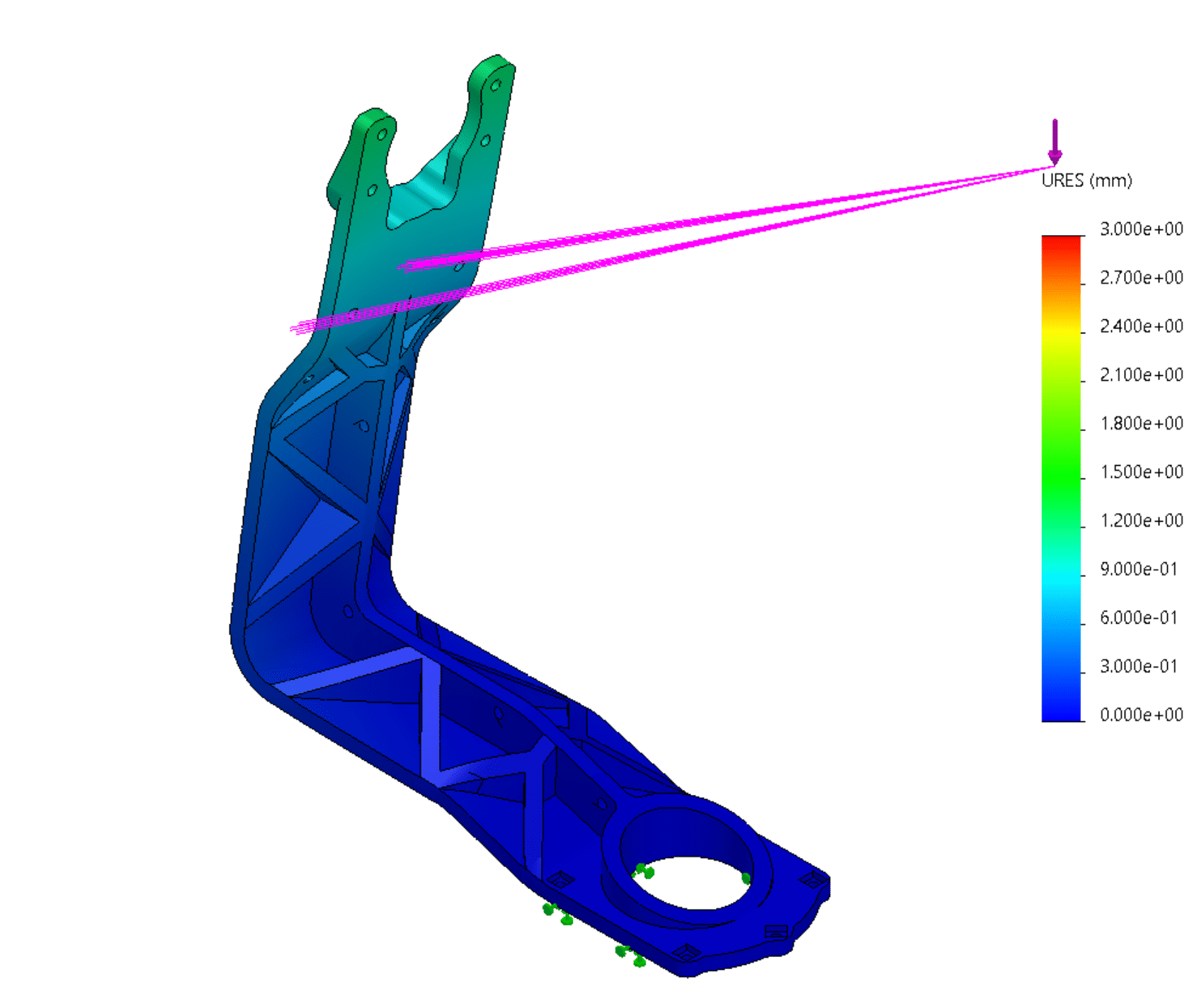
The results show the ribs can decrease the flexing by up to 50%.
Fourth prototype / Revision (version 2)
Preliminary testing of the third prototype showed there is a problem with metal-to-metal contact. The problem is the pins doesnt stay in the plastic wheel, but are pushed out when the worm rotates in one direction and are pushed into the wheel when rotating the other way. In another words, the friction between the plastic and the metal pins is not sufficient to ensure the transfer of force from the worm to the wheel.
Therefore, I have backtracked to using plastic wheel and metal worm. There arises an interesting issue though. Since the wheel is relatively large, there are multiple teeth in contact with the worm, as the wheel rotates. This problem is hard to approximate by rotating some simple object to create a thread/tooth on the wheel.
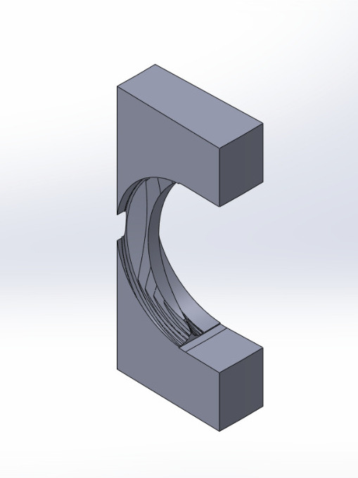
To address this hard (difficult to simplify) problem, I have simply rotated several worm threads around a material and substracted intersecting mass. A single tooth looks like this:
Which is then assembled into a wheel:
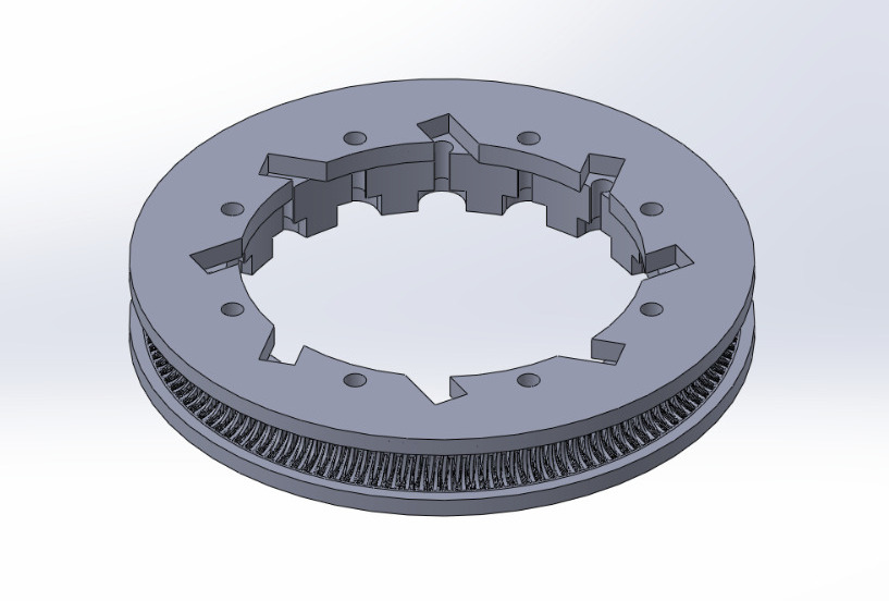
Which is the center-piece of the new axis-mechanism (a.k.a Revision 4, since this is not a prototype anymore):
Third prototype
To step up the game (and address the flexing) I have decided to change the design philosophy. The second prototype taught me a valuable lesson about incorporating a timing belt into a mechanism. For this purpose, the printed tooth need to be quite precise and further, the belt requires sufficient pressure to prevent slipping.
Therefore, for my third prototype, I have decided to remove the timing belt altogether and try a worm-drive instead. There are several reasons I have decided to do it this way:
- Worm-drive requires pressure, rahter than pulling the parts together.
- Worm-drive is self-locking, therefore the motor does not need to consume power when not moving.
- Worm-drive has better torque.
- There is a potential to make the worm-drive metal-to-metal (let me show you below)
Third prototype - assembly
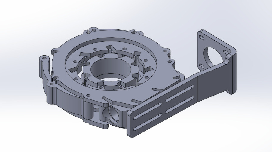
The design logic stay similar to the second prototype, but with motor is now installed 90 degrees relative to the hollow shaft, since the worm-drive requires that. 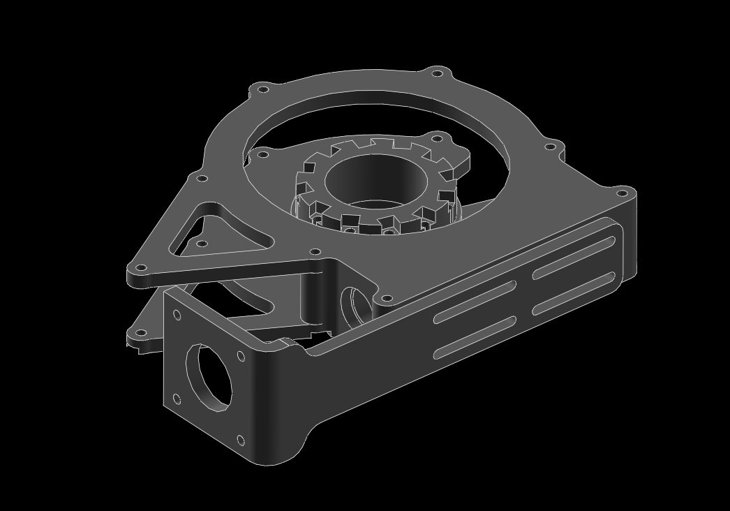
Third prototype - wheel
Most importantly, the wheel now addresses the 4.-th point mentioned above, where the teeth are to be metal pins, rather than printed plastic. 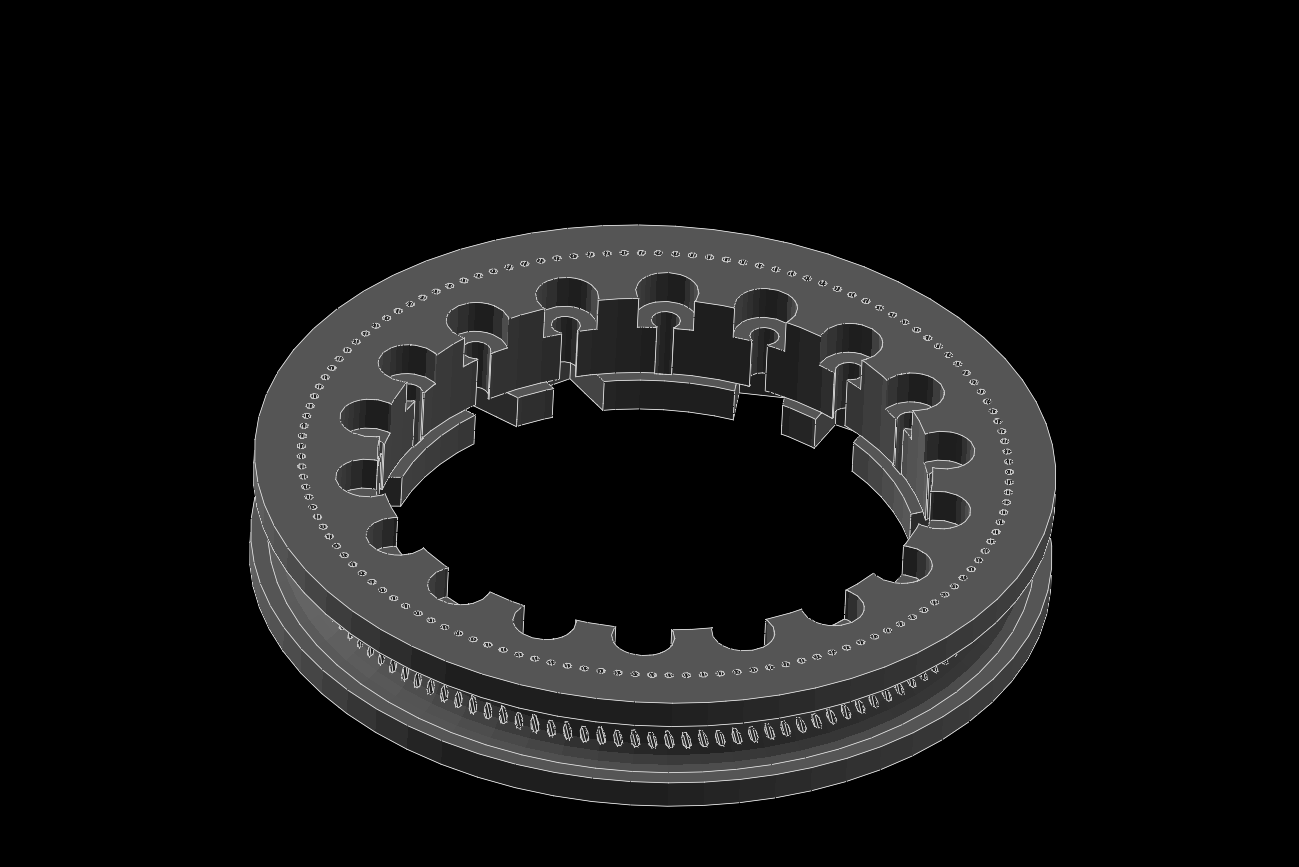
Third prototype - metal-to-metal
The metal-to-metal contact is provided by the metal pins and the T8 trapezoidal theraded rod. I will test 4 different diameters of the metal pins, namely 1.0, 0.9, 0.8 and 0.6 [mm]. At the moment I am in favor of 0.9 and 0.8 [mm] pins, since they dont touch the trapezoidal walls of neighbouring teeths at once, since they hit the “inside” of the metal rod, thus causing minimal friction. 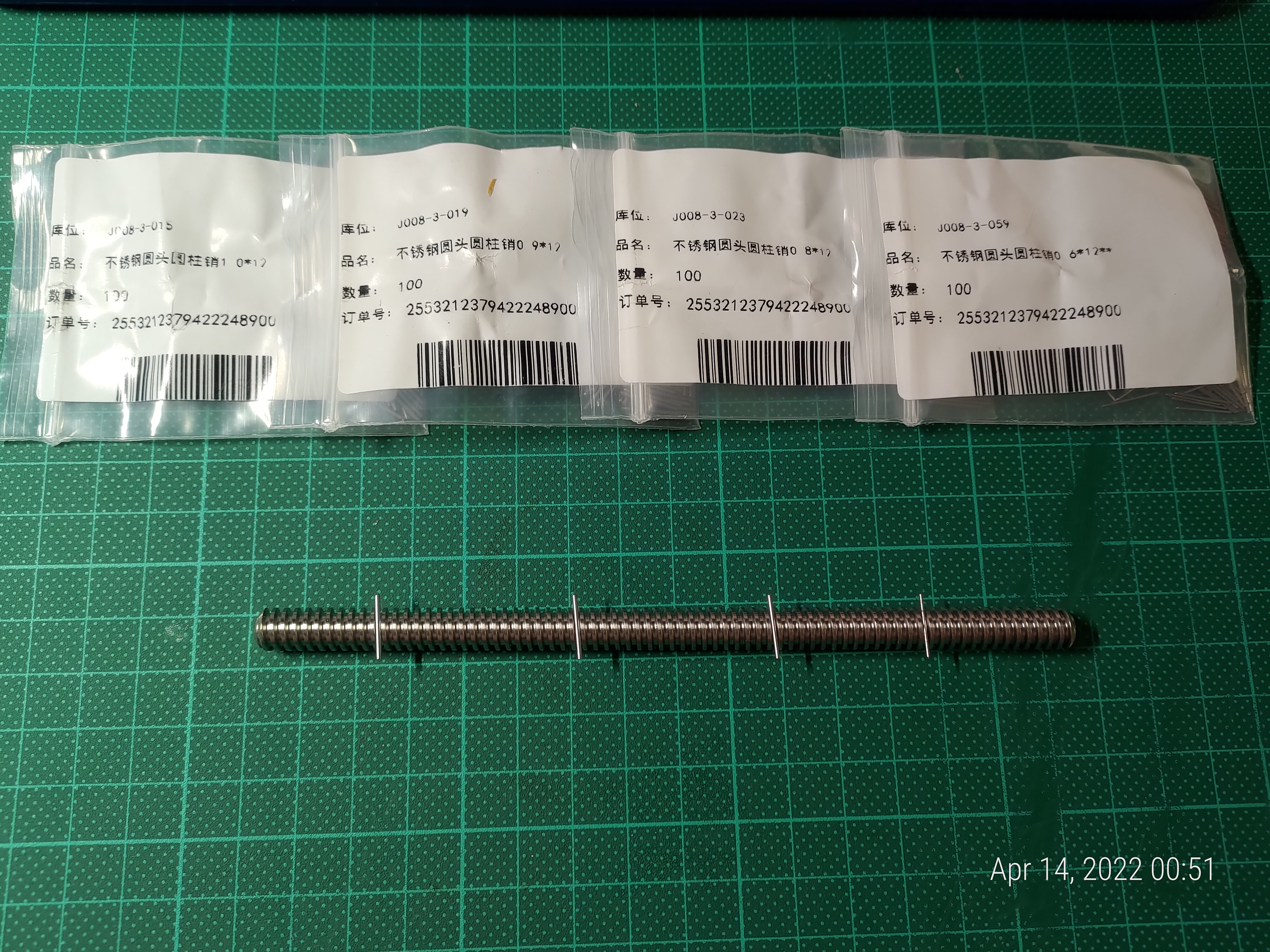
Fourth prototype / Revision (version 2)
Preliminary testing of the third prototype showed there is a problem with metal-to-metal contact. The problem is the pins doesnt stay in the plastic wheel, but are pushed out when the worm rotates in one direction and are pushed into the wheel when rotating the other way. In another words, the friction between the plastic and the metal pins is not sufficient to ensure the transfer of force from the worm to the wheel.
Therefore, I have backtracked to using plastic wheel and metal worm. There arises an interesting issue though. Since the wheel is relatively large, there are multiple teeth in contact with the worm, as the wheel rotates. This problem is hard to approximate by rotating some simple object to create a thread/tooth on the wheel.
To address this hard (difficult to simplify) problem, I have simply rotated several worm threads around a material and substracted intersecting mass. A single tooth looks like this:

Which is then assembled into a wheel:

Which is the center-piece of the new axis-mechanism (a.k.a Revision 4, since this is not a prototype anymore):

Second prototype
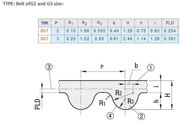
After further investogation, I have realized that I am bound by another component, a timing belt. Another hard dicision had to be done at this point about which geometry of timining belt will this design adhere to. I have settled for the timing belts used commonly used in 3D printers, which follow the standard 2GT, dimensions depicted below.
It is no easy feat to trasfer the dimensions into a 3D program, but after some thinking, and realizing the 3D printer I use add an extra 0.2[mm] to the parts (makes them chunkier), I have decided to adopt the following approximation.
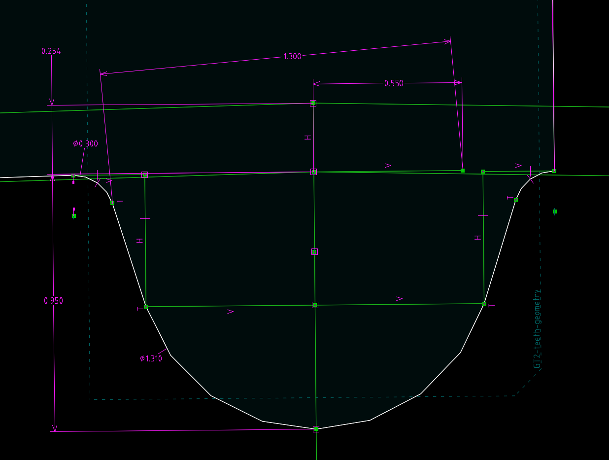
Most of the dimensions are 0.2[mm] larger, such as the h, R3. The R2 is 0.3[mm] larger and the b is 0.15[mm] larger (to compensate the R2). The PLD is without change.
The diameter of the wheel is calculated as
The Ntooth is selected to be 136.
Second prototype - wheel
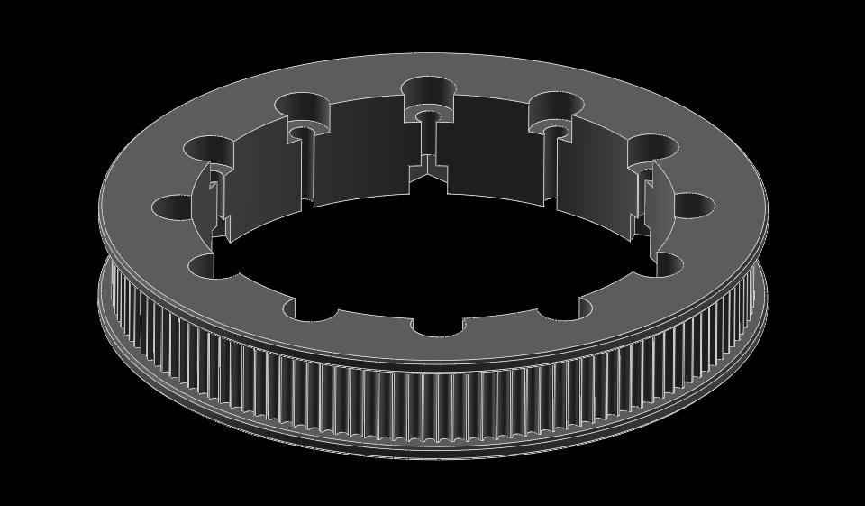
Second prototype - base

Second prototype - top

Second prototype - assembled
The print came in sufficient quality. 
Second prototype - problem with flexing
Apparently, the design is not rigid enough to withstand the pressure from the belt, forcing together the axes of teh motor and the hollow shaft. 
First prototype
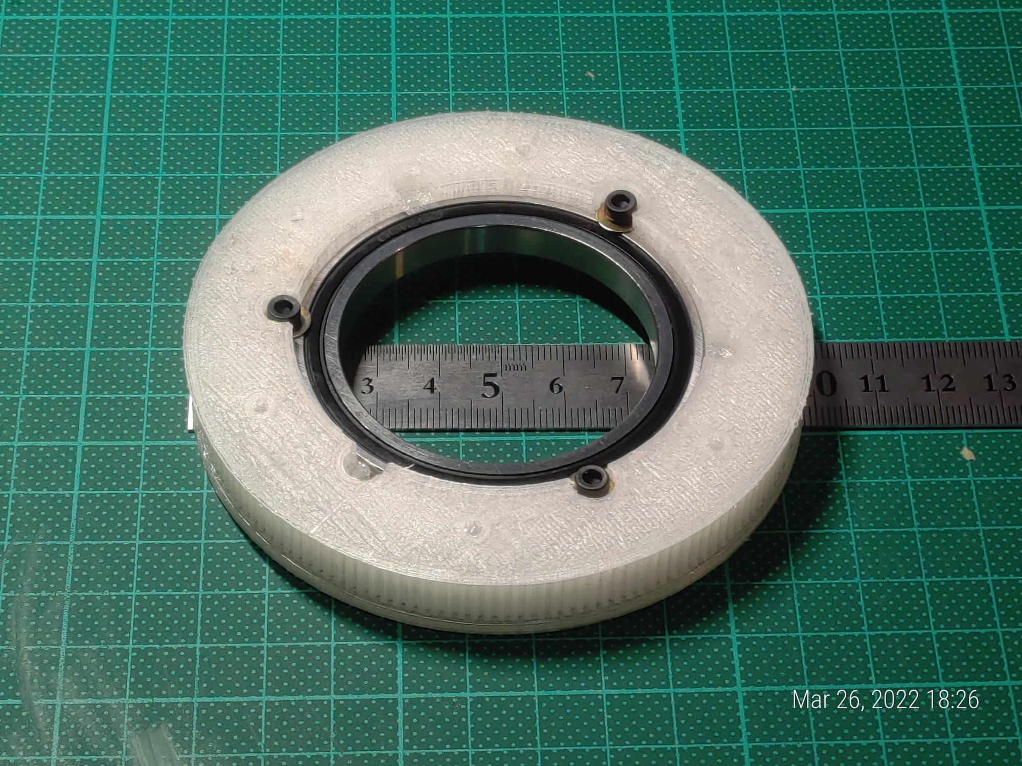
With the basic of-the-shelf parts selected, I have installed SolveSpace and started to work on the hollow shaft gear, that will be driven by the stepper motor.
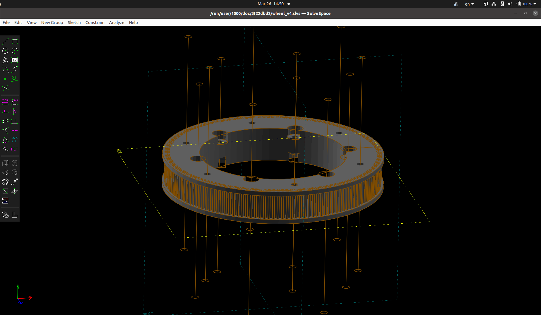
And this is the prototype printed from TPU with 0.2 [mm] layer height with 50 [%] infill.
Assumptions about first prototype
Next step is to agree od dimensions and requirements, such as the hollow shaft width and necessary of-the-shelf parts. I have settled on 2 things:
- Allow myself to visit a local bearing shop and find a standardized bearing (as opposed to bushings in the “Napkin” inception)
- Use NEMA17 stepper motors, since they are lighter and cheaper than NEMA24 and still pack a punch
The visit yielded a bearing 6810, a deep grove radial bearing. As I remember from my bachelor studies, these bearings can take a radial torque and radial pressure without any problem. The dimensions of the bearing are below:
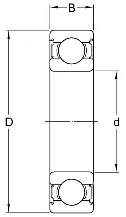
D = 65 [mm]
d = 50 [mm]
B = 7 [mm]
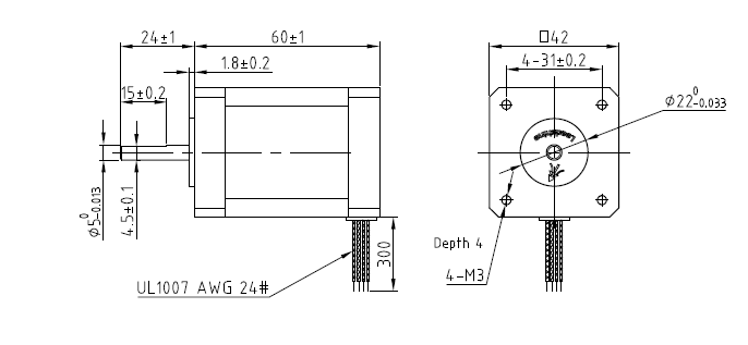
The NEMA17 is a ctually a family of stepper motors, but this one seems particularly well suited for the task in hand, the NEMA17 42CM08 shown below, has torque of 0.8 [Nm] and can be controlled with 1.5 [A] (max 2.5 [A]), which is exactly what the stepper motor driver TMC2209 can handle without any problems.
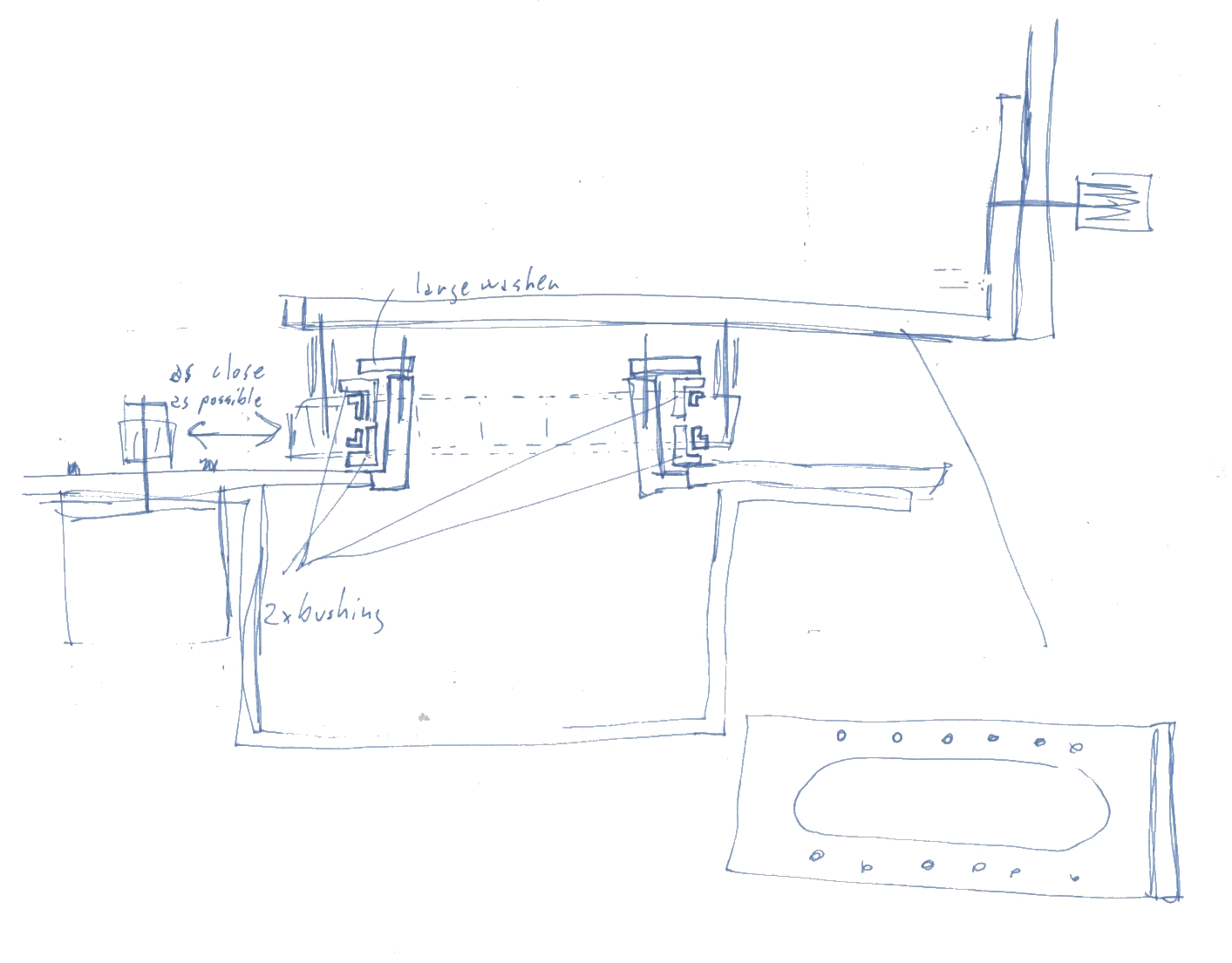
“Napkin” inception of hollow shaft
The idea started during a sleepless night, when my mind was racing for a simple solution to age-old question. What to do with cables when things rotate? The below image is an inception of hollow shaft mechanism, which would be robust yet simple to manufacture using a 3D printer, with minimum of of-the-shelf parts. 